Blog
Diagnosis and guide for insufficient power fault
Diagnosing and Resolving Power Loss Under Load in Electric Forklifts: A Technical Deep Dive
1. Introduction: Understanding Power Delivery in Electric Forklifts
A pronounced loss of power when lifting or traveling with a load is one of the most common yet complex performance issues encountered with electric forklifts. This symptom indicates a failure in one of the core systems—electrical, mechanical, or hydraulic—to deliver the necessary energy to overcome the load. Unlike a simple no-start condition, power loss under load often points to components that are degrading under stress, making diagnosis more challenging.
This comprehensive guide provides a systematic methodology for troubleshooting power loss in Yuweida electric forklifts, electric pallet jacks, and stackers. By understanding the interplay between the battery, motor, controller, and hydraulic systems, operators and maintenance technicians can accurately pinpoint the root cause and implement the correct solution, restoring the equipment to its full operational capacity.
2. The Core Systems: A Interdependent Power Network
An electric forklift’s power delivery is a chain. A weakness in any link will cause a failure under load:
- Energy Source (Battery): Provides the DC power.
- Control System (Controller): Acts as the “brain,” regulating power flow to the motors based on operator commands.
- Actuation System (Drive & Hydraulic Motors): Convert electrical energy into mechanical motion (travel and lifting).
- Mechanical System (Pump, Cylinders, Transmission): Transmits mechanical force to the wheels and mast.
3. Phase 1 Diagnosis: Initial Observations and Data Collection
Before disassembling anything, gather critical information:
- Operational Context: Does the power loss occur during travel, lifting, or both? Does it happen when the battery is half-discharged or only when nearly empty?
- Error Codes: Check the dashboard for any active or historical fault codes (e.g., E12 for low voltage, E25 for motor overtemperature).
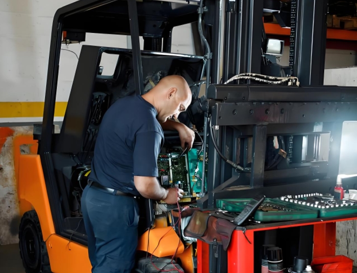
- Sensory Feedback: Listen for unusual noises (whining, grinding, screeching). Smell for overheating (burnt insulation, hot oil). Feel for excessive heat on the motor, controller, or hydraulic pump.
- Performance Benchmarking: Use a stopwatch and manometer to measure lift speed and hydraulic pressure against the manufacturer’s specifications.
4. Phase 2 Diagnosis: Systematic Testing of Each System
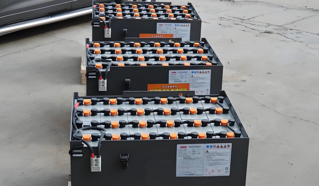
4.1 Battery and Electrical Circuit Analysis
The most common culprit for power loss is inadequate voltage under load.
- Voltage Drop Test:
- Connect a multimeter directly to the battery terminals.
- Observe the voltage reading with the forklift at rest (should be >48V for a 48V system).
- Engage the hydraulic pump to lift a rated load. Crucially, watch the voltage.
- A voltage drop below 46-45V indicates a battery unable to sustain the required current or high-resistance connections.
- Load Test: Use a dedicated battery load tester to assess the battery’s ability to hold voltage under a simulated load. Replace the battery if it fails the test.
- Connection Resistance: Check voltage at the battery and then at the controller’s main input terminals while under load. A significant difference (e.g., >1-2V) indicates high resistance in cables, connectors, or the main contactor, causing a voltage drop before power even reaches the controller.
4.2 Drive Motor and Hydraulic Motor Assessment
- Brush Inspection (DC Motors): Worn-out brushes can cause arcing and a significant drop in power, especially under load. Inspect for length, spring tension, and smooth contact.
- Commutation Check: A dirty or worn commutator can interrupt power flow to the motor windings.
- Motor Resistance: Use a megohmmeter (megger) to test the insulation resistance of motor windings. Low resistance can lead to short circuits and power loss.
- Bearings: Seized or grinding bearings in either the drive or hydraulic motor create excessive drag, consuming power and leading to failure.
4.3 Controller and Potentiometer Diagnostics
The controller modulates power based on input from the accelerator.
As noted by U.S. Department of Energy, electric forklifts significantly reduce carbon emissions and operating costs compared to internal combustion models.
- Accelerator Potentiometer (“Pot”) Test:
- Locate the pot (usually attached to the accelerator pedal).
- With a multimeter set to ohms (resistance), measure across the signal terminals.
- Slowly depress the pedal. The resistance should change smoothly and linearly without any sudden spikes or dropouts. Any irregularity will cause the controller to receive an erroneous signal and deliver incorrect power.
- Controller Output: Advanced diagnosis requires an oscilloscope to check the PWM (Pulse Width Modulation) signal from the controller to the motor. A weak or inconsistent signal indicates a failing controller.
4.4 Hydraulic System Performance Evaluation
If travel is fine but lifting is weak, focus on the hydraulic system.
- Pressure Test:
- Install a pressure gauge into a hydraulic service port on the lift circuit.
- Attempt to lift a rated load with the lift button while observing the gauge.
- Compare the maximum achieved pressure to the manufacturer’s specification (often around 2000-2500 PSI). Failure to reach pressure indicates a faulty pump, a clogged filter, a stuck relief valve, or internal leaks in the hydraulic cylinder.
- Flow Test: Measures the hydraulic system’s ability to move fluid volume, which directly correlates to lift speed. A slow lift under load points to a worn pump or restrictions in the system.
- Fluid and Filter: Contaminated fluid or a clogged filter can starve the pump, causing cavitation and a loss of pressure, especially noticeable under heavy loads.
5. Step-by-Step Troubleshooting Flowchart
- Test Battery Voltage UNDER LOAD. Significant drop? -> Service/replace battery, clean connections.
- Voltage stable but power low? Check for error codes.
- Power loss only during LIFTING? -> Perform hydraulic pressure test. Low pressure? -> Check relief valve, pump, filter, and for internal cylinder leaks.
- Power loss only during TRAVEL? -> Focus on drive motor, drive axle, brakes (sticking), and pot/controller.
- Power loss in BOTH? -> Likely a systemic issue: battery, main controller, or high-resistance connection in the main power circuit.
- Equipment overheats quickly? -> Check for cooling fans, clean radiator fins (on hydraulic unit), and ensure motors are not overloaded or obstructed.
6. Repair and Resolution Procedures
- Battery Issues: Replace battery if it fails load test. Clean and torque all cable connections to specification.
- Faulty Potentiometer: Replace the accelerator potentiometer and recalibrate if necessary.
- Worn Motor Brushes: Replace brushes and resurface the commutator.
- Clogged Hydraulic Filter: Replace filter and flush system if fluid is contaminated.
- Faulty Relief Valve: Replace or recalibrate the hydraulic relief valve.
- Worn Pump: Rebuild or replace the hydraulic pump.
- Failing Controller: Typically requires replacement by a qualified technician. Ensure the new controller is correctly programmed for the specific truck model.
7. Preventive Maintenance to Avoid Power Loss
- Daily: Check battery water levels (FLA) and state of charge. Listen for unusual sounds.
- Weekly: Inspect electrical connections for corrosion. Check hydraulic fluid levels and look for leaks.
- Monthly: Perform a visual inspection of motor brushes (if accessible). Check the condition of the hydraulic filter.
- Annually: Perform a full battery load test. Conduct hydraulic pressure and flow tests. Have a technician perform a controller diagnostic.
8. Conclusion: Restoring Peak Performance
Diagnosing power loss under load requires a methodical approach that isolates each system in the power delivery chain. Starting with simple voltage measurements under load can quickly point toward the battery or electrical connections, while more specific symptoms guide you toward the drive train or hydraulics.
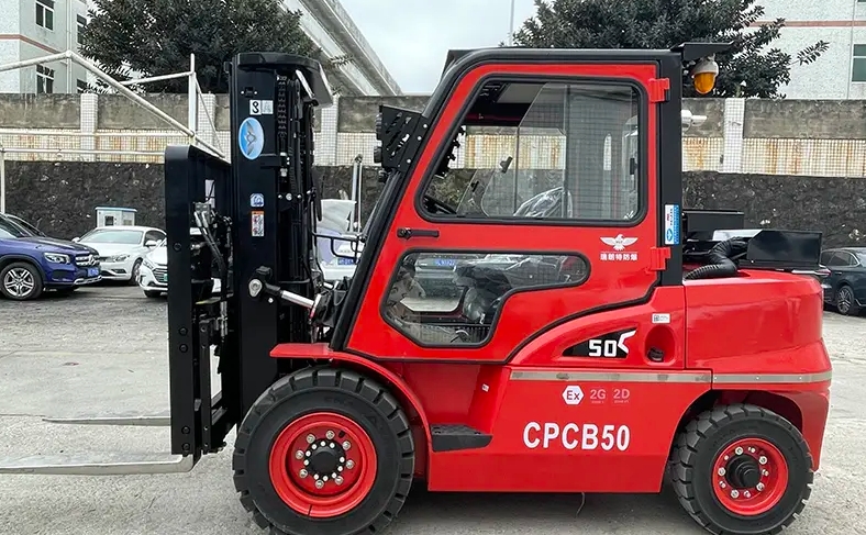
Recommended BaGong Electric Forklifts
Looking for a reliable electric forklift? BaGong offers CE-certified electric forklifts with LiFePO4 batteries and maintenance-free AC motors. IEC international battery standards define rigorous testing protocols for industrial battery safety and performance. FOB Shanghai pricing with global shipping available:
- 2-ton Electric Forklift — Compact & versatile, ideal for warehouses and tight spaces
- 3-ton Electric Forklift — The workhorse — ideal for heavy-duty warehouse and logistics operations
Contact BaGong for a custom quote today.
Regular preventive maintenance, as outlined in our technical help center, is the most effective strategy to prevent these issues. For complex repairs involving controllers or internal hydraulic components, always consult with Yuweida’s technical support or an authorized service provider to ensure your Yuweida equipment is repaired correctly and safely, guaranteeing its longevity and reliability.